
Ask ten people what size cable to run to your fridge and you’ll get ten answers, most of them wrong, and a fair few of them dangerous. The problem isn’t that cable sizing is hard. It’s that almost everyone is answering the wrong question.
There are two separate limits on a cable, and they have nothing to do with each other. Most advice only considers one of them.
Limit one: how much current before it melts
This is the current rating printed on the packet. It’s a thermal limit — push more than this through the cable and the copper heats up faster than it can shed heat, the PVC softens, and eventually you have a fire in a confined space full of gas bottles and foam insulation.
This rating is independent of length. A one-metre run and a ten-metre run of the same cable have the same thermal rating.
Limit two: how much voltage you lose getting there
Copper has resistance. Current flowing through resistance drops voltage. The longer the run and the higher the current, the more voltage you lose before it reaches the load.
This limit scales directly with length, and it is almost always the binding constraint in a caravan. In a 240V house, losing 3 volts is 1.25% and nobody notices. In a 12V system, losing 3 volts is 25% and your DC-DC charger never reaches absorption voltage, your fridge compressor cycles on low-voltage cutout, and your auxiliary battery never actually gets full.
This is the one people get wrong. They look up the amp rating, see 70 amps, and run it eight metres to the back of the van — and then can’t work out why the battery won’t charge past 80%.
The Australian sizing trap: mm is not mm²
Before the table, the thing that catches the most people.
Australian automotive cable is sold by trade name — 3mm, 4mm, 6mm. That number is the outside diameter of the insulated core, not the copper cross-section. Narva’s own part numbering confirms it: the size digit refers to the diameter of each core as measured in mm.
So “6mm automotive cable” does not contain 6mm² of copper. It contains roughly 4.6mm². If you sized your inverter feed assuming 6mm², you’re about 25% short before you’ve even started.
Heavy cable is sold differently again — as B&S (Brown & Sharpe), which is the same numbering as AWG. 8 B&S is 8 AWG. Smaller number, more copper. And worth knowing: 10 B&S is thinner than 6mm auto cable, despite sounding chunkier.
Australian B&S battery cable often carries slightly less copper than the true AWG figure — 8 B&S is commonly 7.0mm² where true 8 AWG is 8.37mm². Check the manufacturer’s stated mm², not the gauge label.
12V cable size chart
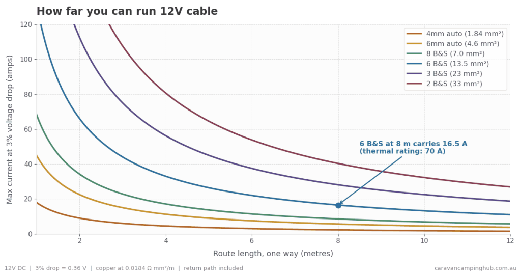
Route length below means the one-way distance from source to load. The current travels there and back, so the actual copper in circuit is double — the calculation already accounts for this. Measure the path the cable physically takes, not the straight line.
| Cable | Copper (mm²) | Outer dia. (mm) | Continuous rating (A) | Max amps @ 2m (3% drop) | Max amps @ 8m (3% drop) |
|---|---|---|---|---|---|
| 2mm auto | 0.64 | 2.0 | 6 | 3 | 0.8 |
| 3mm auto | 1.13 | 3.0 | 10 | 5.5 | 1.4 |
| 4mm auto | 1.84 | 4.0 | 15 | 9 | 2.3 |
| 5mm auto | 3.25 | 5.0 | 25 | 16 | 4 |
| 6mm auto | 4.6 | 6.0 | 30 | 22 | 5.6 |
| 8 B&S | 7.0 | 5.5 | 45 | 34 | 8.6 |
| 6 B&S | 13.5 | 7.3 | 70 | 66 | 16.5 |
| 3 B&S | 23 | 10.2 | 100 | 112 | 28 |
| 2 B&S | 33 | 11.2 | 120 | 161 | 40 |
| 0 B&S | 50 | 13.0 | 150 | 245 | 61 |
| 00 B&S | 65 | 16.6 | 180 | 318 | 79 |
Outer diameters are typical for single-core V90 PVC automotive and battery cable and vary between manufacturers — measure yours before ordering glands, conduit or grommets. Current ratings are nominal and depend on the standard used (see below).
AWG, B&S and mm² conversion
First thing to clear up: AWG and B&S are the same system. Brown & Sharpe is the original name for what most of the world now calls American Wire Gauge. 8 B&S is 8 AWG. There is nothing to convert between them — if a supplier lists both, they are listing the same number twice.
What does need converting is gauge to mm², and that’s where Australian cable gets slippery. The gauge implies a nominal copper area, but the cable actually sold at that gauge often contains less.
| AWG (= B&S) | Nominal copper for that gauge (mm²) | Australian cable sold at this size | Copper you actually get (mm²) |
|---|---|---|---|
| 20 | 0.52 | 2mm auto | 0.64 |
| 18 | 0.82 | — | — |
| 16 | 1.31 | 3mm auto | 1.13 |
| 14 | 2.08 | 4mm auto | 1.84 |
| 12 | 3.31 | 5mm auto | 3.25 |
| 10 | 5.26 | 6mm auto | 4.6 |
| 8 | 8.37 | 8 B&S | 7.0 |
| 6 | 13.3 | 6 B&S | 13.5 |
| 4 | 21.2 | 4 B&S | 21 |
| 3 | 26.7 | 3 B&S | 23 |
| 2 | 33.6 | 2 B&S | 33 |
| 1/0 | 53.5 | 0 B&S | 50 |
| 2/0 | 67.4 | 00 B&S | 65 |
Compare the second and fourth columns. 6mm auto sits at the 10 AWG mark but gives you 4.6mm² against a nominal 5.26mm². 3 B&S gives you 23mm² against a nominal 26.7mm² — about 14% short. 8 B&S is 16% short.
None of this is anyone cheating. Stranded automotive cable is built to different standards than solid drawn wire, and the trade sizes have their own history. But if you size a circuit off a gauge number and an AWG chart, you will end up with less copper than you calculated for. Work from the manufacturer’s stated mm², which is the number in the fourth column and in the chart above.
Read those last two columns again
6 B&S is rated 70 amps continuous. At an eight metre route length it will carry 16.5 amps before you’ve lost 3% of your voltage.
Not because the cable is unsafe at 70A over that distance — thermally it’s fine. But the thing on the end won’t work properly. That gap between 70 and 16.5 is the entire reason people end up with systems that pass an inspection and still don’t perform.
Note also that the two are not interchangeable pieces of information. Voltage drop scales directly with copper cross-section, so the last two columns track the mm² column almost exactly. Thermal ratings don’t behave that way — the amps per mm² a cable will take falls as the cable gets bigger, from roughly 6.5 A/mm² for 6mm auto down to under 3 A/mm² for 00 B&S, because a thick conductor sheds heat less efficiently than a thin one. You can’t infer one limit from the other.
The continuous ratings in the table are deliberately conservative. Published figures vary widely between suppliers, and there are too many variables in a real install — ambient temperature, whether the run is bundled or in free air, which standard the rating was calculated against — to treat any single number as authoritative. If you are anywhere near the limit, size up.
Why the amp rating changes depending on who you ask
You’ll see the same cable rated 50A by one supplier and 35A by another. Neither is lying.
The Australian standard rates cable to a maximum conductor temperature of 60°C at 25°C ambient. It’s increasingly common to see cable rated instead to the JIS/JASO standards, which allow 80°C conductor temperature — a higher number for exactly the same cable.
Some catalogues also quote intermittent ratings (five-second duty for starter circuits) alongside continuous ratings without labelling which is which. Always check whether the figure you’re reading is continuous.
The maths, if you want to do it yourself
For DC:
Voltage drop = (2 × L × I × ρ) ÷ A
- L = route length in metres (one way)
- I = current in amps
- ρ = resistivity of copper, roughly 0.0184 Ω·mm²/m at working temperature
- A = copper cross-section in mm²
The 2 accounts for the return path. Rearranged to find the cable size you need:
A = (2 × L × I × ρ) ÷ allowable drop
Worked example
A 40A DC-DC charger, 5.5 metres from the vehicle battery to the caravan. Target 3% drop, which on 12V is 0.36V.
A = (2 × 5.5 × 40 × 0.0184) ÷ 0.36 = 22.5mm²
That’s 3 B&S. Not 6 B&S, which is what most people run, and not the 8 B&S that comes in a lot of kits. If you ran 6 B&S on that circuit you’d see about 0.6V drop — enough that a lithium battery may never reach its absorption target.
Note also that this is one-way to the van. If your earth returns through the chassis and drawbar rather than a dedicated cable, you’ve added resistance you can’t calculate and can’t see. Run a dedicated negative.
How much drop is acceptable?
Two working numbers:
- 3% for anything that charges or regulates — DC-DC chargers, solar controller to battery, battery to inverter, anything where the voltage itself is the signal.
- 10% for non-critical loads — interior LED lighting, USB outlets, a water pump. They’ll still work; the lights will be slightly dimmer.
- Watch the startup surge — some loads draw far more on startup than in steady state. A diesel heater glow plug is the classic example, pulling several times its running current for the first minute. Size the cable for the surge, not the average.
If you’re not sure which bucket something falls into, use 3%. The cost difference over a few metres is a coffee.
What else eats into your margin
Ambient temperature. Ratings assume 25–30°C ambient. A cable run through a roof cavity in Queensland in February is nowhere near that. Copper resistance rises roughly 0.4% per °C, so a 60°C cable run has about 14% more resistance than the table assumes.
Bundling. Cables in a loom or conduit can’t shed heat to open air. Multi-core and bundled runs derate significantly against single-core-in-free-air figures.
Connections. Every crimp, terminal, fuse holder and plug adds resistance. Anderson plugs are a common culprit — a 50A grey Anderson on a 40A DC-DC circuit is marginal, and a poorly crimped one will get warm and get worse. Crimp properly with the right die, don’t solder high-current automotive terminations, and check them after the first few thousand kilometres of corrugations.
Age and corrosion. Salt air and water ingress degrade terminations over time. A circuit that measured fine at install may not now.
Sizing the fuse, not just the cable
The fuse protects the cable, not the appliance. It should be rated below the cable’s thermal capacity and as close as practical to the power source — the point of a fuse is to protect the run if it chafes through somewhere along its length, which does you no good if the fuse is at the far end.
Sizing the cable for voltage drop usually means you end up with cable far heavier than the load requires. That’s fine. Just don’t then fit a fuse sized to the cable — size it to the load.
A quick way to sanity-check an existing install
You don’t need to trust anyone’s numbers, including ours. Put a multimeter across the source and another across the load, under real load, and compare. Or measure at the load, turn the load on and off, and watch the difference.
If you’re losing more than a few tenths of a volt on a charging circuit, your cable is undersized — regardless of what the packet said.
Before you start
Everything above is 12V DC. It is general information to help you understand how the calculation works, not a design for your specific van.
Anything involving 240V — inverters feeding fixed wiring, caravan mains circuits, RCDs, appliance outlets — is licensed electrical work in every Australian state and territory. Do not do it yourself. It’s not a legal technicality either; a caravan is a metal box you sleep in with your family.
Even on the 12V side, high-current battery circuits carry enough energy to start a fire or weld a spanner to a chassis in seconds. Fuse close to the battery, use the right lugs and dies, and if you’re unsure, get an auto electrician to look over it. We can explain the principles — we can’t inspect your rig.
 12V or 24V – Which Voltage Should you Choose for your 4×4, Camper or Caravan?
 LiFePO4 or Lithium-ION. Understanding the Difference of LiFePO4 and Lithium-ion Batteries
 How to get mail and parcels on the Road. A guide to receiving mail while you are travelling Australia in a Caravan.
 What is an Inverter and what size Inverter do I need for my Caravan 2026?
 Choosing the Right Auxiliary Battery for Your Caravan, Camper, RV or 4×4 (2026 Guide)
 How to Install a Diesel Heater in your Caravan or Camper, a step-by-step guide with pictures 2026

